
Windpower@LTEtt
In 2007, the idea arose to add a wind turbine to the photovoltaic system on the roof of the Lycée Technique d’Ettelbruck.
During the 2007/2008 academic year, two Year 6 pupils designed the system as part of their “Energy and Environment” course. The installation site was determined, a suitable wind turbine was chosen and a mast appropriate for the roof construction was specified.
Technical data:
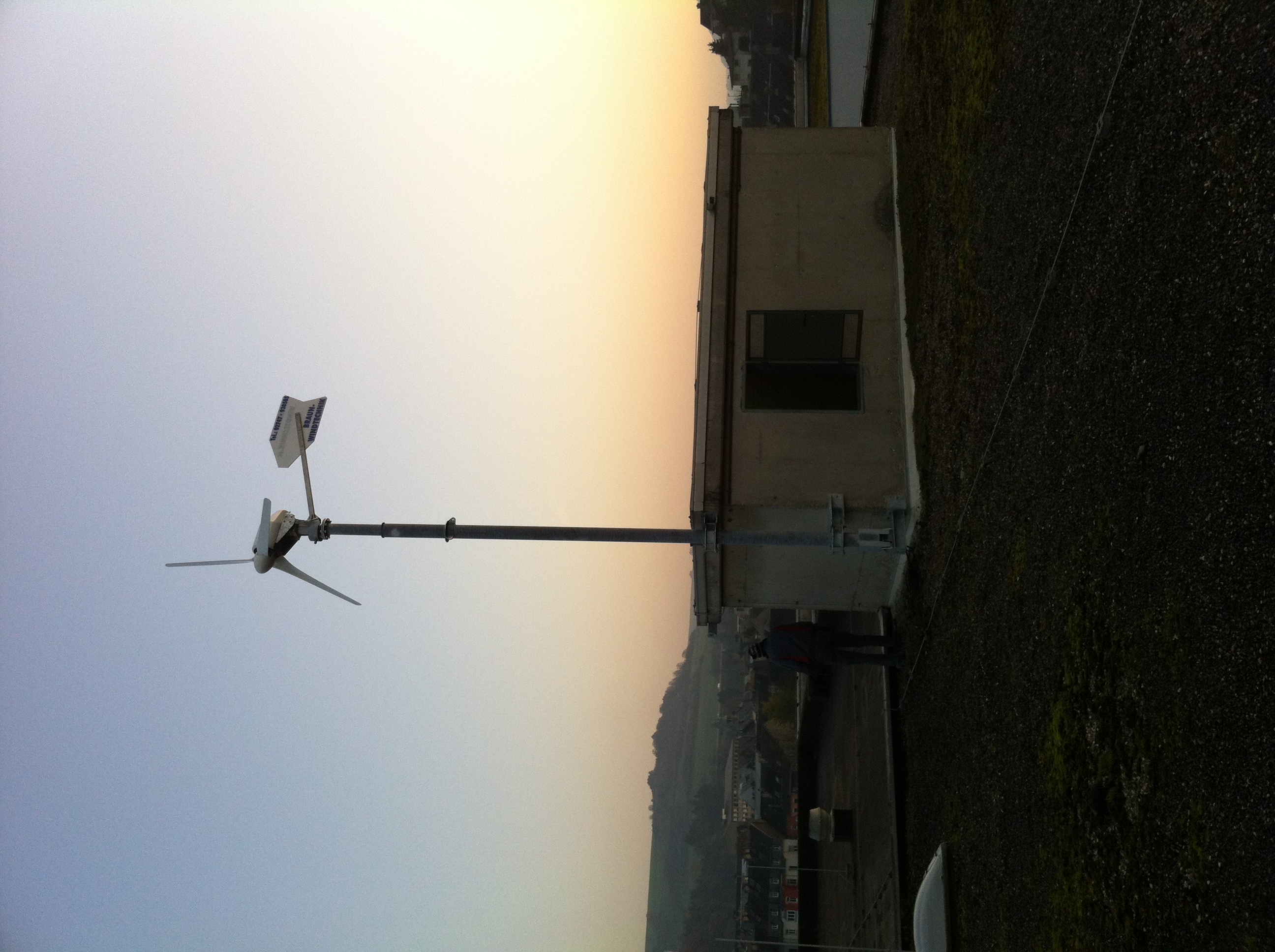
Wind turbine
The wine turbine is a device made by Braun Windturbinen and features the following technical data:
| Antaris 1.7kW | |
| Rotor | 3 GFK – rotor blades; Ø 3.50m; low-noise due to winglets; stall controlled |
| Generator | gearless; brushless; 3-phase; permanent magnet rotor (NdFeB); 10-pole |
| Power transmission | slip rings / cable |
| Voltage | up to 500 VDC |
| Rated output | 1700 W |
| Start-up speed | 2.4m/s |
| Nominal speed | 12m/s |
| Survival speed | 55m/s |
| Storm protection | Voltage monitoring; helicopter position |
| Weight | 89kg |
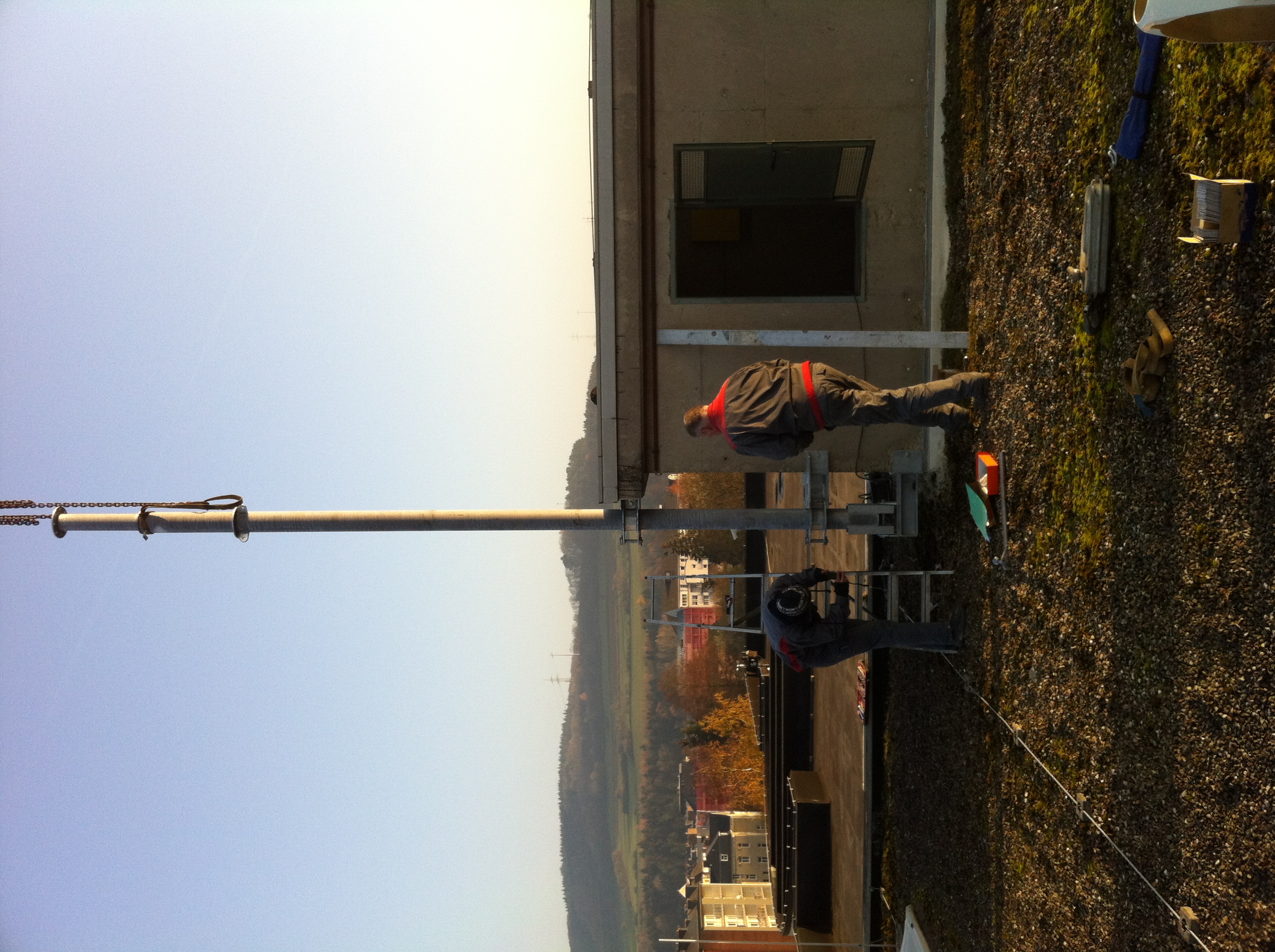
Mast
A tilt mast was chosen to allow any potential changes to be made to the installation. The mast was designed and constructed by metal manufacturer Thill in Asselborn.
Mast technical data
- Mast made of tubular steel, Ø139.7 x 5.0mm – Quality S235
- Mast head with flange Ø220 x 10.00 – identical to foot flange WKA
- Mast foot with hinge, for folding with the help of a hoist or similar
- 2 heavy-duty fastening brackets mounted to the building, with clamping screw and safety bolts featuring a padlock to prevent unauthorised unscrewing of the brackets
- maximum wind resistance of the installation according to manufacturer specifications………………………………………………………………….. 40 kN
- weight of installation, manufacturer specification………………….. 0.75 kN
- maximum wind pressure to mast tube, derivation see appendix 08 ……………………………………………………………………… 858 kN/m2
Support reactions
Perpendicular to the hinge
Fv= 0.75 + 6.0 x 0.166 = 1.75 kN
Horizontal to the brackets
FH=(1.40×3.93+0.858×0.14×3.932 /2)/1.25= 5.14kN
Bending moment in tube at upper mount
Moment caused by wind
M=1.40×3.93 +0.858×0.14×3.932 /2 = 6.43kNm
Deflection
f1=1/3x140x393.03 /2.10/106 /480.5= 2.81cm f2=1/8×85.8×0.14×3.93×393.03/2.1/106 /480.5= 0.36cm f= 3.17 cm
Secondary moment caused by displacement M’=(0.75+1⁄2×6.0×0.166)x3.17×10-2 =0.04kNm
Bending stress in tube
σ= 1.50 x 6.50 x 103 / 68.80 = 142 N/mm2 (1.50 = dynamic coefficient)
Safety against the stress limit k= 240 / 142 = 1.69
Electrical installation
The electricity generated is fed into the public grid via a grid inverter (Windy Boy 1100).
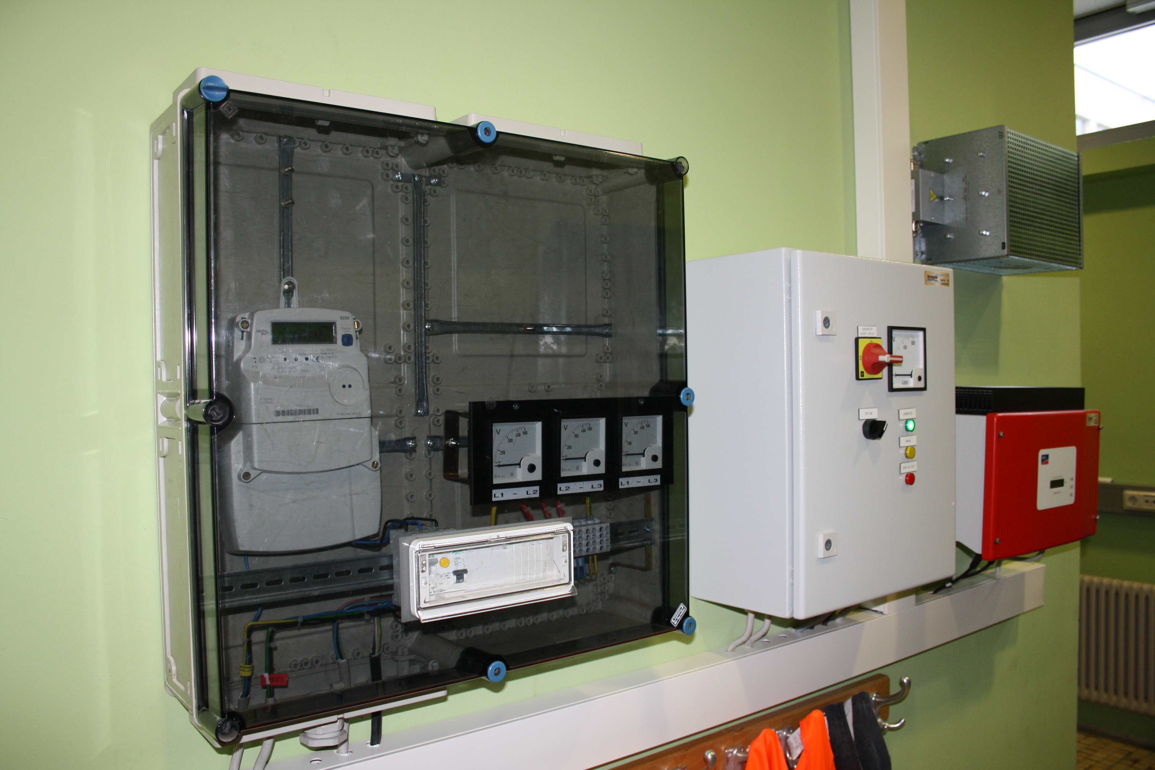
(caption)
Meter cabinet, frequency converter and inverter
The electrical energy generated is reimbursed by the energy supply company.
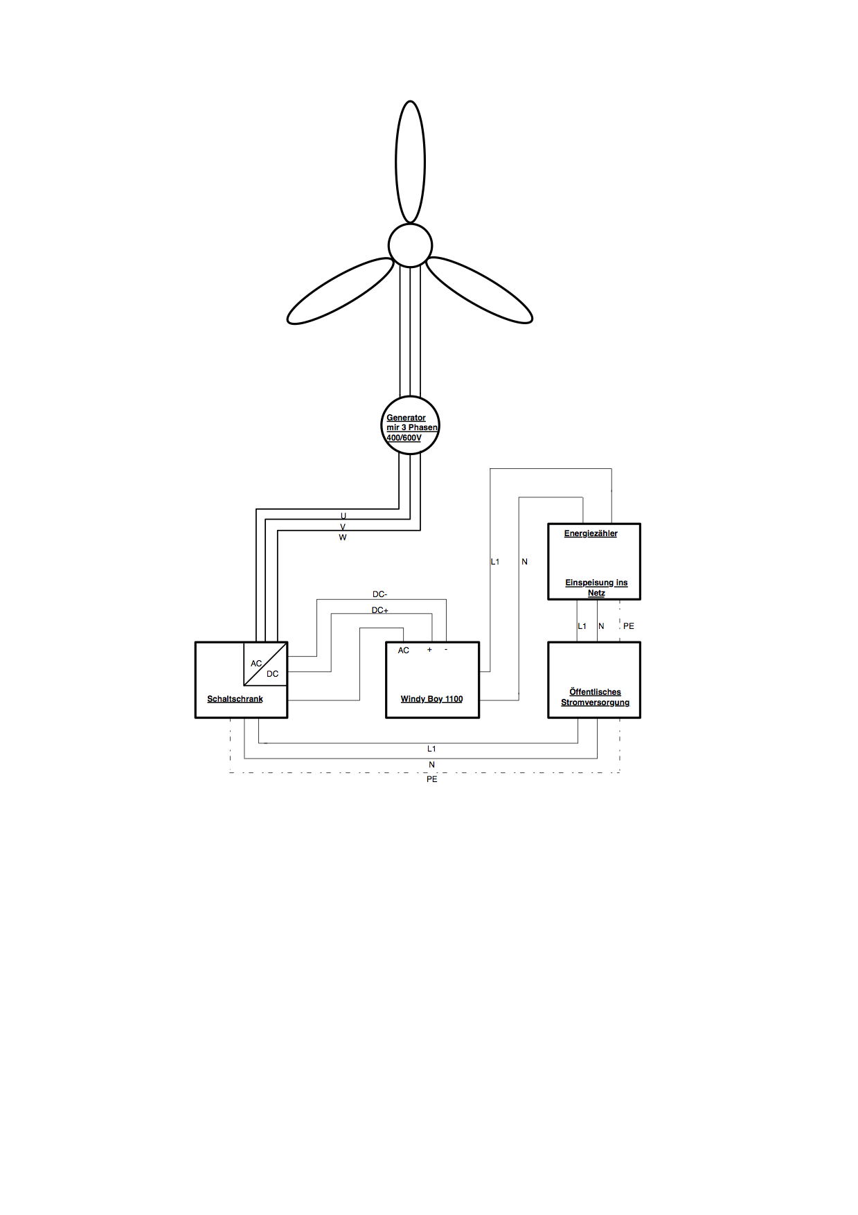
(diagram)
Generator mit 3 Phasen = Generator with 3 phases
Schaltschrank = control cabinet
Energiezähler = energy meter
Einspeisung ins Netz = feeding into the grid
Öffentliches Stromversorgung = public electricity supply